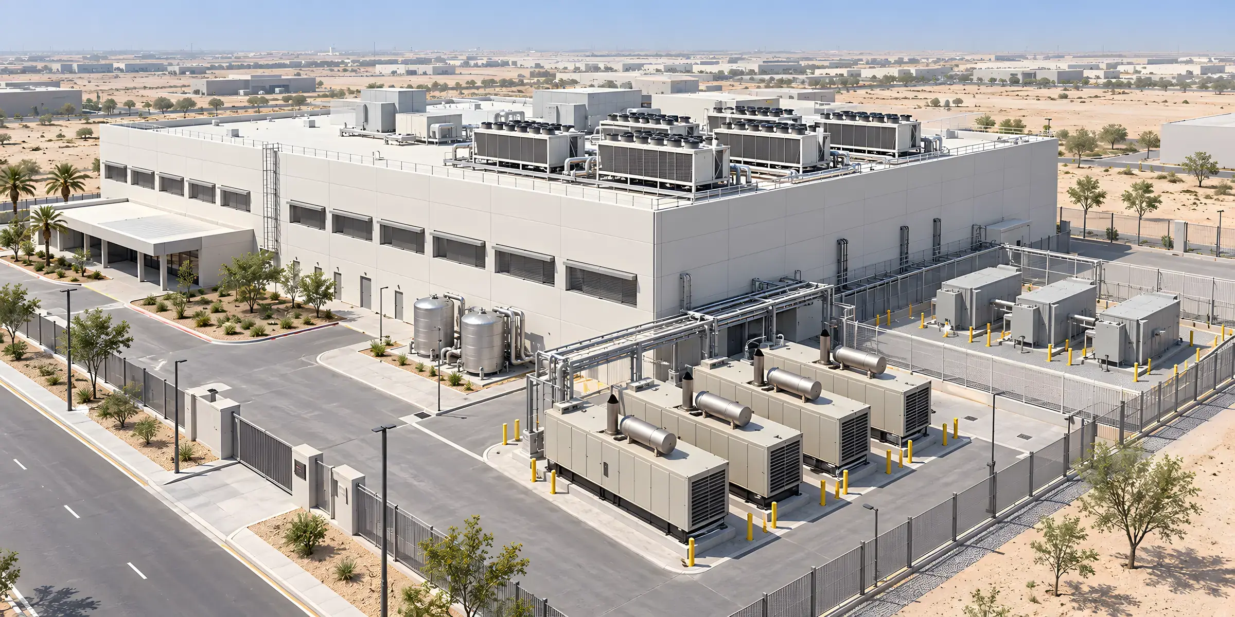
Services / Design
Design & Engineering
Coordinated MEP engineering for resilient critical facilities.
When clients need this
Clients use this service when a facility needs engineering depth beyond general building services: where uptime, maintainability, phased capacity and a certification target affect every choice, and where the client needs a design basis of its own against which every later decision is checked.
Mechanical, electrical, fire, security, low-current and telecommunications engineering for data centers, from the design basis to construction documents. The disciplines are developed as one system. The facility is sized for its load profile, its climate and its operating model, and every path is drawn so that it can be maintained with the load still supported.
What UBIK provides
- Design basis: load profile, resilience objective, ASHRAE envelope, climate design conditions, phasing and operating model
- Concept, schematic and detailed design packages: single-line diagrams, cooling schematics, layouts, calculations and specifications
- Power and cooling topology studies with the failure and maintenance states drawn out
- Fire protection, security, low-current and telecommunications coordination
- Design review and maintainability review with a closed comment register
Method
The steps in the order the work happens. Each step closes with a record the client keeps.
- 01
Write the design basis first
IT load by phase and density, the resilience objective in Tier terms, the ASHRAE environmental envelope, the climate design conditions, the operating model and the expansion path. Signed by the client before the first drawing.
- 02
Decide the topology by its failure states
Power and cooling paths are drawn in normal operation, then with each element out for maintenance, then in failure. A topology survives on paper only if every state keeps the load supported with the margin the objective requires.
- 03
Coordinate the disciplines in one model
Electrical, mechanical, fire, security and telecoms are developed together, with plant rooms, risers, routes and clearances resolved in the model before they are resolved on site.
- 04
Specify for the design conditions
Equipment is specified by performance under the design conditions, including part load and the hottest hour, with the acceptance tests that will prove it written into the specification.
How the system fits together
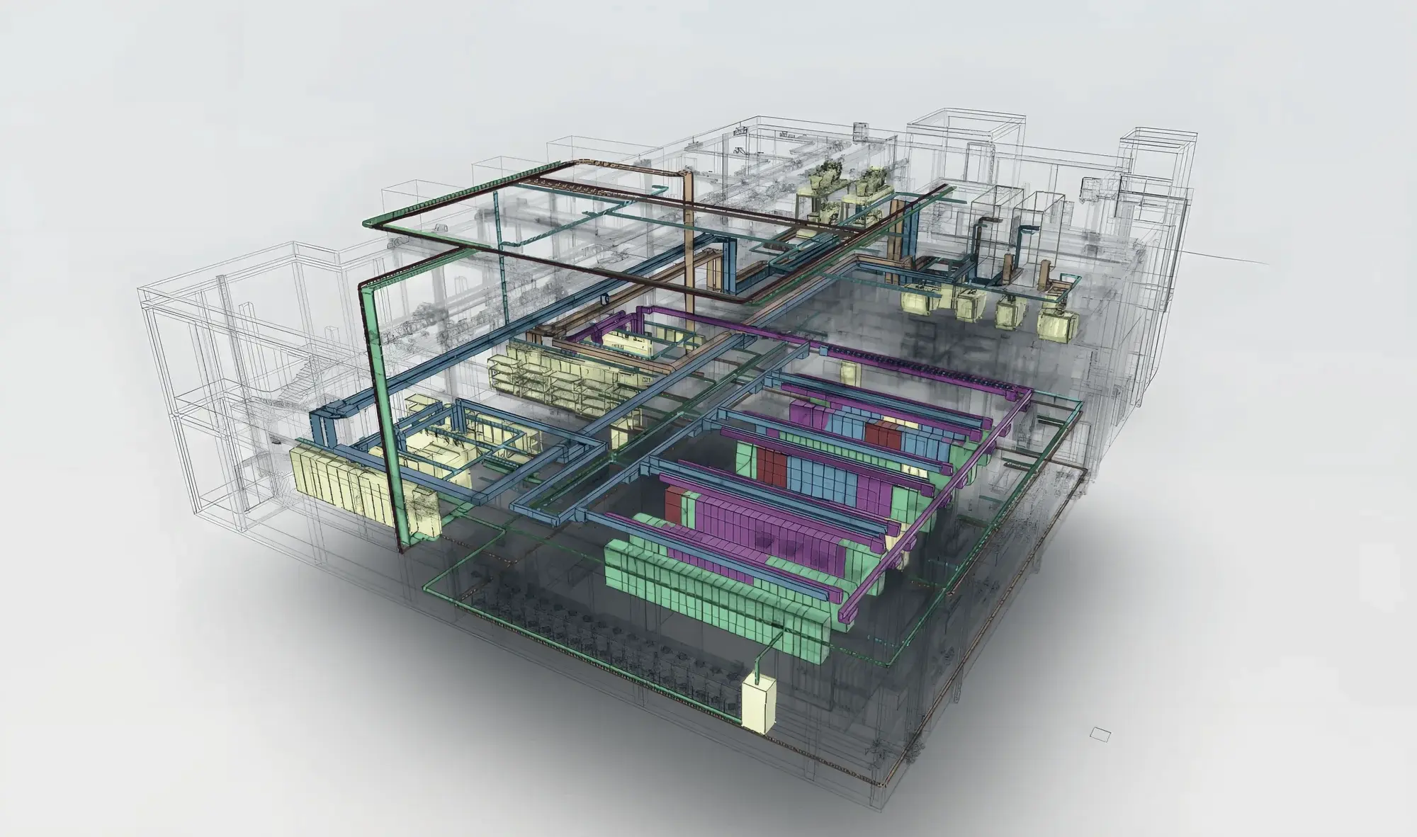
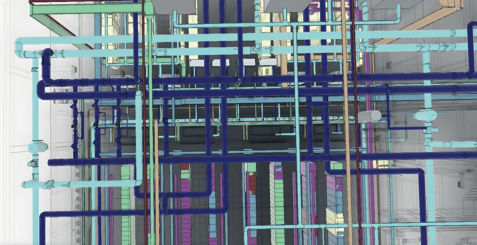
The system or process this service works on, drawn by UBIK.
From the design model
Views exported from UBIK’s coordinated models, with the systems shown by colour and the building as a wireframe. Sites are not identified.
In depth
How UBIK approaches this service, in the detail a technical buyer evaluates. Each part opens separately.
01The design basis is the client’s document
A critical facility is designed from a short list of inputs that must be confirmed rather than assumed: the IT load by phase and by rack density, the resilience objective in Tier terms, the ASHRAE environmental envelope the IT will be held in, the climate design conditions for the site, the operating model and the expansion path. UBIK writes those into a design basis the client signs before the first drawing, and every later decision is traced back to it.
The design basis is also where the operating scenarios are made explicit. Besides normal operation, it lists the conditions the topology and the control philosophy have to be tested against: planned maintenance on each element, the loss of a utility feed, a chiller failure in the hottest hour, and a phase of the building running at a fifth of its design load for two years. The list is written before the design begins.
02Topology decided by its failure states
Redundancy is easy to write on an equipment schedule and hard to keep in the field. A pair of chillers on a common header with the isolation valves in the wrong place is one chiller for maintenance purposes. Two UPS systems fed from one low-voltage board share that board’s outage. UBIK draws the power and cooling paths in normal operation, then with each element out for maintenance, then in failure, and only a topology that keeps the load supported in every state with the margin the objective requires is carried forward.
The drawings that come out of that exercise, single-line diagrams with the maintenance states marked, cooling schematics with every isolation point, and the operating narratives that describe each transfer, are the same documents a certifier will ask for. Designing for the failure states and designing for certification are one piece of work.
03One model, every discipline
Mechanical, electrical, fire protection, security, low-current and telecommunications systems are developed together in one coordinated model. Plant rooms, risers, cable routes, pipe racks, busway, containment and the clearances around every piece of equipment are resolved in the model, so that the replacement route for a transformer or the pull-out space for a chiller coil is a dimension on a drawing rather than a discovery on site.
Maintainability is reviewed as a discipline of its own: can each item be isolated, accessed, removed and replaced with the facility running, by the team that will do it, with the tools that team will have. The review produces a register, and the register is closed before the design is issued.
04Specified for the site’s design conditions
Equipment is specified by what it must do under the site’s design conditions, including the hottest hour and the part loads of the early phases where most facilities spend their first years, and with the factory and site acceptance tests that will prove it written into the specification. A chiller’s catalogue capacity at a reference ambient is not a design input in a climate where the design dry-bulb is above 45 °C.
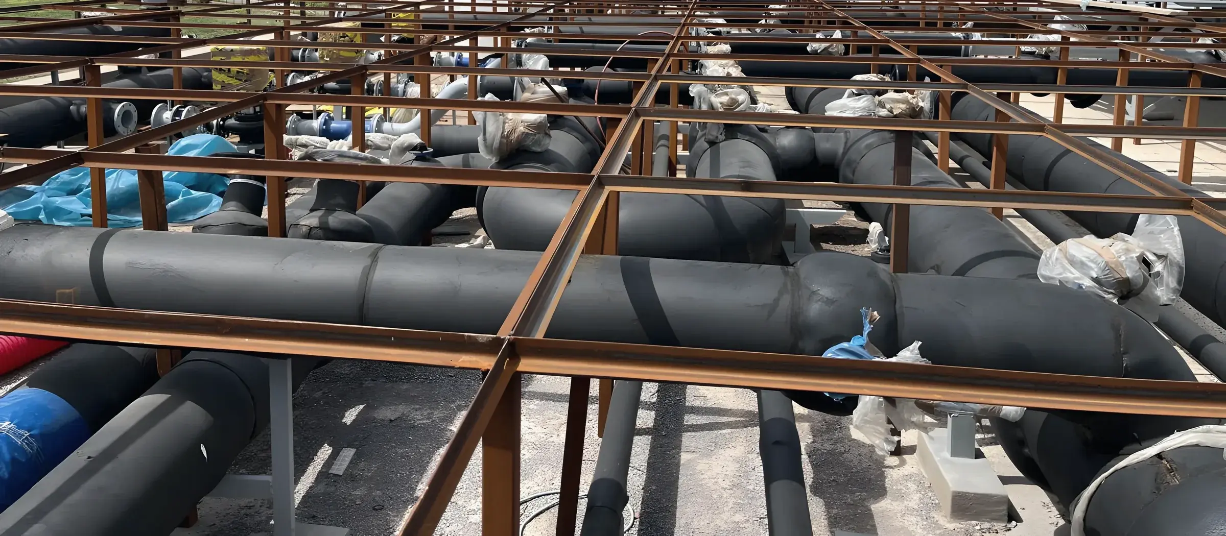
In practice
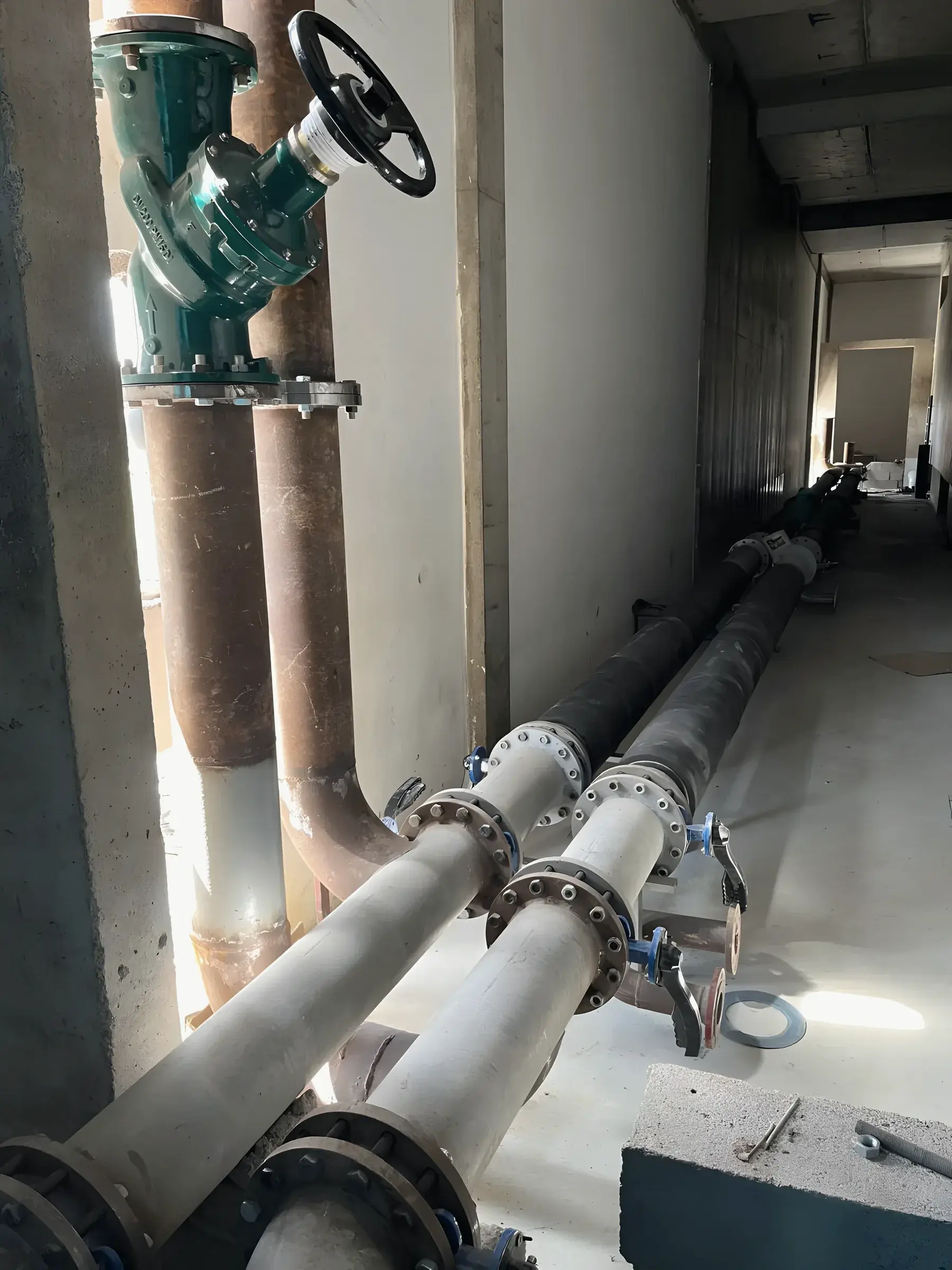
The photographs are from UBIK’s own work. Sites and clients are not identified.
Risks reduced
- Discipline designs that each work alone and fail together under a maintenance state
- A topology whose redundancy exists on the schedule but not in the field: shared headers, common busbars, single control paths
- Late redesign when an untested access or replacement route meets the installed equipment
Questions from clients
Questions clients ask before an appointment, with UBIK’s answers.
- Does UBIK produce the full construction documents or review a contractor’s design?
- Both, and the boundary is set at appointment. On a design-and-build project UBIK writes the employer’s requirements and the design basis, then reviews the contractor’s design against them. On a traditional project UBIK produces the design packages for tender and construction.
- How does UBIK design for a hot climate?
- Heat rejection is sized from the site’s climate file for the design dry-bulb and wet-bulb hours with the resilience margin, economiser hours are counted rather than assumed, water risk is assessed with the utility, and the plant is checked at the part loads of the early phases, where most facilities actually run.
- Which design stages does UBIK take a project through?
- Design basis and concept, schematic design, detailed design and construction documents, and construction-stage support: submittals, substitutions and site queries. Each stage closes with a reviewed package and a register of the decisions and assumptions carried forward.
Standards and frameworks
Each is applied alongside local codes and the project brief.
Related references
Each card states whether the work is current UBIK work, a confidential current engagement or leadership experience.
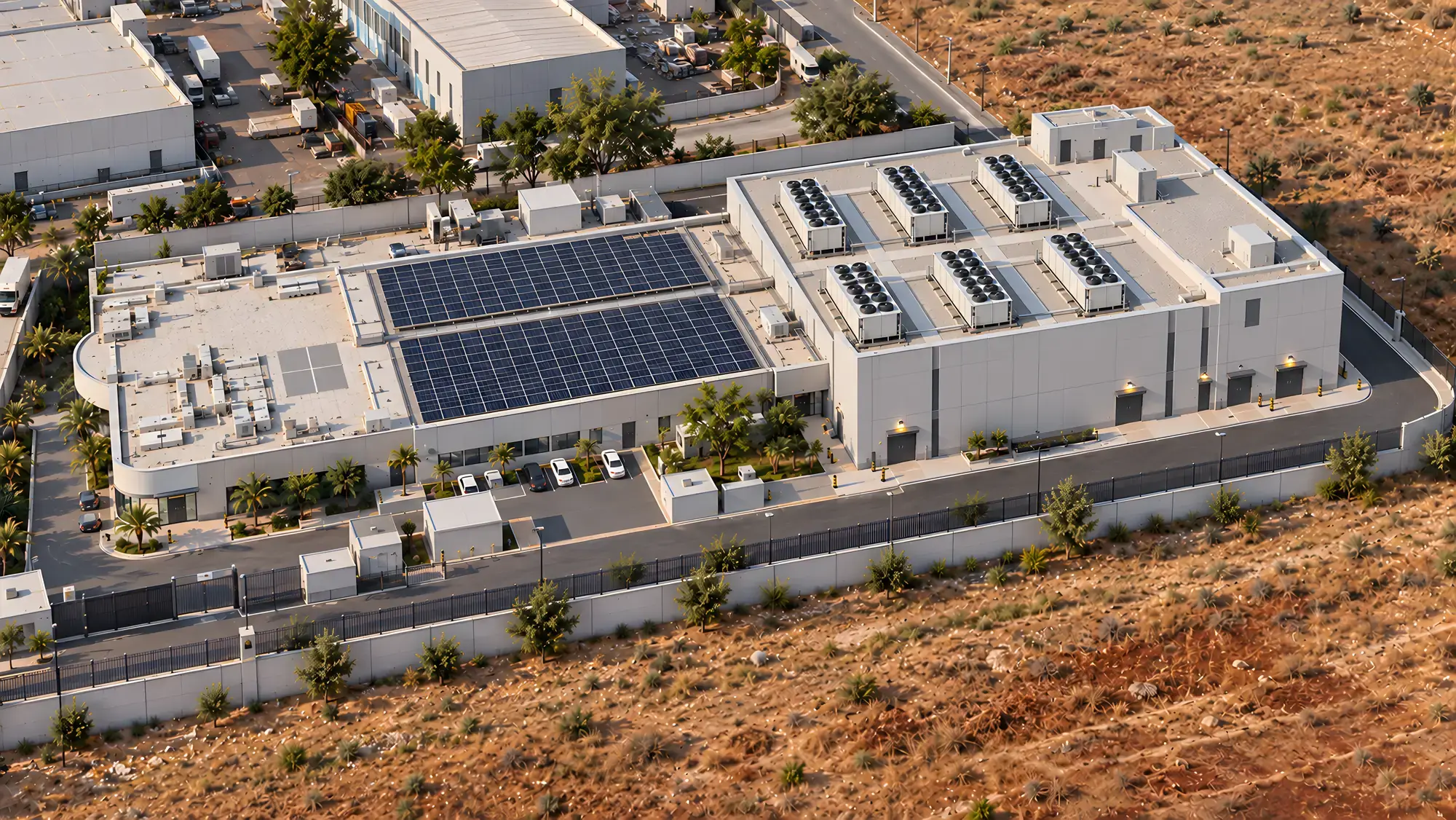
Casablanca, Morocco
N+ONE CMN, Casablanca
Tier III · 4 MW IT, phased · 8 MW across CMN and STT
Full design, construction direction, commissioning and Tier III certification management for N+ONE’s CMN hyperscale data center, 4 MW of IT load at 15 to 17 kW per rack.
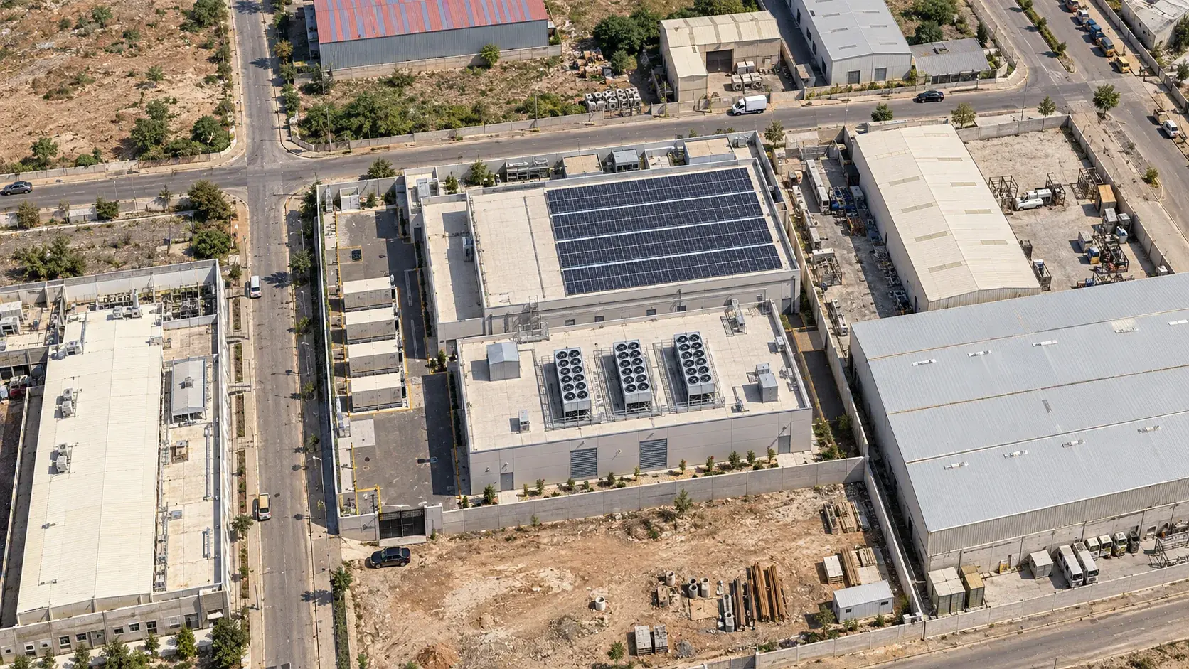
Settat, Morocco
N+ONE STT, Settat
Tier III · 4 MW IT, phased · 8 MW across CMN and STT
Full design, construction direction and commissioning management for N+ONE’s STT hyperscale data center at Settat Park, 4 MW of IT load, developed in parallel with CMN.
Ghana
Confidential public-sector client
Concept and schematic design, every discipline, of a public-sector data center in Ghana with 45 kW per rack zones, in progress.
Further reading
Articles by the UBIK principals on this subject.
- energy / 6 min readEnergy performance: look beyond a single PUEPUE is useful when its measurement boundary and load assumptions are understood. This article sets out how to read a quoted figure and what it leaves out.
- certification / 6 min readTier certification: what an owner is actually buyingThis article sets out what each Tier certification verifies, what it does not, and the four decisions about resilience that belong in the design brief.
Next step
Enquiries about this service.
An enquiry should state the project stage, the location, the resilience objective and the technical decision that needs review.